Step 1: Prepare the installation tools before installation
It is required special installation tools for installation and commissioning of diesel generator set, here are the standard tools for reference:
1.Tool box 11. 8mm Solid wrench
2.27’’ Vigorous plier 12. Hammer
3.3x Cutting pliers 13. 4’’ Cinquefoil screwdriver
4. Flat nose pliers 14. 6’’ Cinquefoil screwdriver
5. Belt wrench 15. 4’’ Screwdriver
6. 8’’ Monkey wrench 16. 6’’ Screwdriver
7. 17mm Solid wrench 17. 334-4’’ Hex tools
8. 14mm Solid wrench
9.13mm Solid wrench
10.10m Solid wrench
Step 2: Environmental inspection before installation
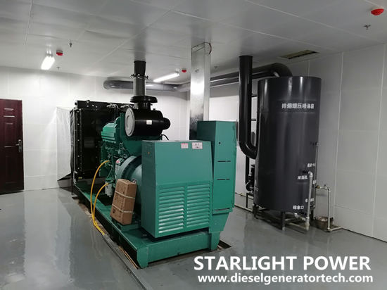
Design reasonable installation environment: indoor and outdoor machine room. Meet the maintenance and operation requirements, ventilation and heat dissipation requirements, environmental noise requirements, smoke and heat insulation requirements, and the architectural standard requirements for the arrangement of seismic accessories. It is beneficial to give full play to the excellent characteristics of diesel generator set, prolong the service life and improve the reliability.
Layout principle of diesel generator set machine room
1.Except one end of the cooling water tank, the distance between the other sides and the wall of the machine room should not be less than 1m, so as to facilitate operation and maintenance in the future.
2.The distance between the height of the machine room roof and the top of the genset height shall not be less than 1.5 m. Generally, the room height shall not be less than 4.5 m, which is the min. distance that must be maintained for ventilation and heat dissipation of the genset and maintenance of lifting parts.

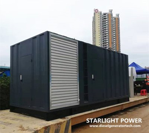
Outdoor layout principle of diesel generator set machine room
1.No barriers are allowed in each 1m space for operation and maintenance in future.
2.One end of the cooling water tank should not face the closed obstacles.
Step 3: Inspection of foundation(Environmental inspection)
1.The strength of the foundation must be able to support the wet weight (including unit, fuel oil and cooling water) and dynamic load of the unit.
2.The mass of the foundation can bear 2-5 times of the total mass of the unit, and a smaller value can be taken for the high-speed unit.
3.Each side of the foundation shall be 200 mm beyond the base of the unit.
4.The foundation shall be 200 mm above the ground to prevent water immersion.
Step 4: Open package to inspect the goods
1.According to the project implementation business process.
2.Check whether the package is damaged and verify the package number and quantity.
3.Do not damage the machine when unpacking. The order is to remove the top plate and then the side plate.
4.Check all units and accessories according to the unit list and packing list.
5.Check whether the main dimensions of the unit and accessories are consistent with the drawings.
6.Check the unit and accessories for damage and corrosion.
7.After unpacking, the unit should be kept in a horizontal position.
Step 5: installation of diesel generator set--hoisting
1.The outdoor soundproof genset can lifted to the foundation directly by forklift.
2.The unit must be kept in horizontal position during hoisting.
3.When hoisting diesel generator set, the steel wire rope with sufficient strength shall be used at the lifting position of the unit, which shall not be set on the shaft, and the oil pipe and dial shall be prevented from being damaged. The unit shall be lifted according to the requirements.
4.Refer to the technical operation and maintenance manual of the unit.

Step 6: Installation of diesel generator set--Horizontal positioning
1.Place the level meter on the upper end face of the soundproof cover (i.e. machining reference plane) to check the level.
2.The horizontal accuracy is the longitudinal and transverse horizontal deviation of 0.1 mm per meter. There should be no space between the foundation and the base frame, so that the force is uniform.
3.After confirm level position, do horizontal positioning operation to fix genset by using expansion bolts through the fixed holes on the unit base frame.
Step 7: Installation of fuel pipe
1.The distance between the bottom of the external fuel tank and the high-pressure oil pump shall not be higher than 1.5m, and the min. distance shall not be less than 2m.
2.The vibration will cause the sediment to rise, and the heat source may reduce the diesel engine power. So the installation position should avoid the heat source and vibration source as far as possible.
3.Install according to the fuel line connection diagram of the unit.
4.Lead plated water pipe or lead plating device shall not be used in fuel system.
5.The delivery oil pipe shall be no less than 50 mm higher than the bottom of the oil tank and away from the drain valve.
6.The installation must ensure that there is no leakage in the fuel pipeline.
Comments
Post a Comment