Common trouble of Yuchai 4D24/4D24T diesel engine and removal methods
Note: This manual describes some typical engine operation problems, the reasons and the solutions.
Warning: Implementation of this chapter of the fault diagnosis and elimination steps may result in machinery damage or personal injury or even death. It must be by trained technicians implement fault diagnosis and troubleshooting work. For not listed in this chapter the diagnosis and exclude steps and symptoms, please contact Raywin.
To make a fault diagnosis, please follow the following recommendations:
1) Careful analysis of the problem before action;
2) Start with the most easy and obvious place;
3) Find the root causes and eliminate the oroblem.
In order to find fault in time, protect the diesel engine, greatly shorten the maintenance time, improve the utilization efficiency of the diesel engine, RAYWIN 4D24, 4D24T engine's ECU is with fault diagnosis function. ECU can make diagnose judgement by analyzing electric signals, to diagnose the most electronic components and a few mechanical component failures. Once the fault of electronic control system is detected by ECU, it will produce a corresponding fault code and save the information into ECU memory.
I. Fault indicator
1) These fault indicator is located on the dashboard:
2) These are generally red color (for more details please refer to machinery manual);
3) These are self-checking after electricity, fault indicator light turns off after 2 seconds;
4) Light turns on once the failure of electrical failure system appears;
5) General fault, fault indicator lighting;
6) Serious faults, fault indicator flashing;
7) Fault disappears, the malfunction indicator light off automatically.
II. fault flash code reading method
Read fault flash code method th rough fa ult indicator lamp:
1) These are the ignition switch in the ON place;
2) with or without load;
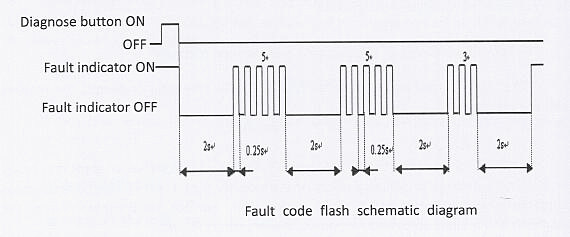
3) Press diagnose button to activate the fault diagnosis flash code;
4) Each operation gets one fault flash code, all fault flash codes can be got one by one;
5) Fault flash codes include current and historical code;
6) Reading the code after cleaning, which is the current fault code.
For example, using the above method to read ECU memory warning lamp line fault, fault flash code 553, the flashing way of the fault indicator light is as follows:

III. the method of cleaning the historical fault code
In practical application, it can remove the historical fault code in ECU memory conveniently and quickly by using diagnose button, the detail is as follows:
Press diagnosis request button;
Put the ignition button to the OFF place for more than 18 seconds, until ECU power off;
Put the ignition button to the ON place, ECU power on;
ECU power on for 6 seconds (4~8 seconds), then release of the diagnosis request button.
Comments
Post a Comment