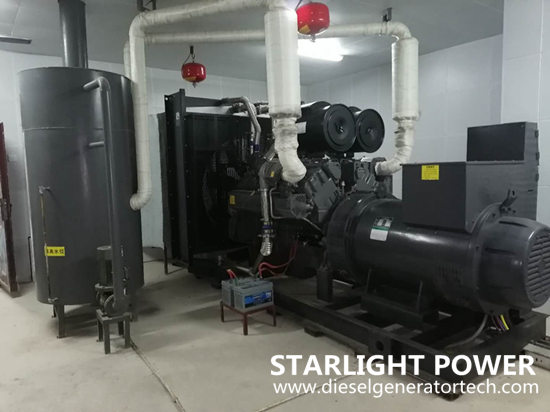
This article is mainly about dealing with typical fault codes of diesel generator set, hope it is helpful to you.
1.Fault code 131,132
131: No. 1 accelerator pedal or lever position sensor circuit, voltage above normal value or short circuit to high voltage source.
132: No. 1 accelerator pedal or lever position sensor circuit, voltage under normal value or short circuit to low voltage source.
(1)Fault phenomenon
The voltage on accelerator pedal position sensor 1 circuit is high(fault code 131) or low (fault code 132).
(2)Circuit description
The throttle position sensor is a Hall effect sensor connected to the accelerator pedal, the signal voltage from the throttle position sensor to the ECM will change when the accelerator pedal is depressed or released. When the accelerator pedal is at 0, the ECM will receive a low voltage signal; When the accelerator pedal is at 100%, the ECM will receive a high voltage signal. The accelerator pedal position circuit includes 5V power circuit, return circuit and signal circuit. The accelerator pedal has two position sensors which are used to measure the throttle position. Both position sensors receive 5V power from the ECM and the corresponding signal voltage from the ECM according to the accelerator pedal position. The No. 1 throttle position signal voltage is twice of the No. 2 throttle position signal voltage. This fault code is set when the ECM senses a signal voltage that is below the normal operating range of the sensor.
(3)Component location
The accelerator pedal or lever position sensor is located on the accelerator pedal or lever.
(4)Reason
Accelerator pedal or lever position signal circuit short circuit to battery or + 5V source;
Broken circuit in accelerator pedal circuit in harness or connector;
Accelerator power supply short circuit to battery;
Faulty accelerator pedal or lever position sensor;
Wrong installation of accelerator pedal during maintenance.
(5)Solution ways
Check whether the wiring of accelerator pedal is correct;
Check whether the accelerator pedal position sensor and connector pins is damage or looseness;
Check whether the accelerator pedal position sensor voltage and return voltage are about 5V;
Check if the ECM and 0EM harness connector pins are damage or looseness;
Check if the ECM and 0EM harness circuit is open or short.

2.Fault code 331, 332
331:The current in No.2 cylinder injector solenoid driver is below normal value or open.
332: The current in No.4 cylinder injector solenoid driver is below normal value or open.
(1)Fault phenomenon
The engine may misfire or run rough; the engine is weak under heavy load.
(2)Circuit description
When the injector solenoids control the amount of fuel injected, the electronic control module (ECM) supplies power to the solenoids by turning off the high and low switches. There are two high-end switches and six low-end switches in the ECM.
The injectors of cylinders 1, 2 and 3 (front) share a single high-end switch inside the ECM, which connects the injector circuit to the high-pressure power supply. Similarly, four, five and six cylinders (back row) share a single high-end switch inside the ECM. Each injector circuit in the ECM has a dedicated low-end switch, which forms a complete circuit to the ground.
(3)Component location
The engine harness connects the ECM to three through connectors for the injector circuits that are located in the rocker arm housing. The internal injector harness is located under the valve cover and connects the injector to the engine harness at the through connector. Each through connector supplies power to both injectors and provides a return circuit.
(4)Reason
331 fault alarm caused by abnormal operation of cylinder 1, 2 and 3 injectors;
332 fault alarm caused by abnormal operation of cylinder 4, 5 and6 injectors;
Virtual connection of engine injector connecting harness or injector connecting wire;
The injector solenoid is damaged (high or low resistance);
ECM internal damage.
(5)Solution ways
Check the fuel injector harness for virtual connection or short circuit;
Check the pins in the injector connection harness for a short circuit caused by oil contamination.
3.Fault code 428
428: Water in fuel indicator sensor circuit, voltage above normal value or short to high source.
(1)Fault phenomenon
Engine water in fuel fault alarm.
(2)Circuit description
The water in fuel (WIF) sensor is attached to the fuel filter and the electronic control module provides a 5V DC reference signal to the water in fuel sensor. After the water collected in the fuel filter covers the sensor probe, the water in fuel sensor makes the 5V reference voltage grounded, indicating that the water in fuel filter is high.
(3)Component location
Water in fuel sensor is generally provided by 0EM and synthesized on vehicle fuel prefilter.
(4)Failure reason
Alarm caused by too much water in prefilter;
Alarm caused by disconnection of harness connector of connecting sensor;
Alarm caused by reverse connection of connecting harness;
Alarm caused by wrong sensor model
Broken in harness, connector or sensor return or signal circuit;
The signal wire is shorted to the sensor power supply.
(5)Solution ways
Check whether the vehicle prefilter has accumulated water;
Check whether the sensor matches;
Check whether the sensor wiring is correct and whether the connector contacts;
Generally, the alarm "428" will be given when two wires are short circuited.
Starlight Power company produces diesel generator set with many kinds of engine, such as Cummins, Volvo, Perkins, Deutz, Yuchai, Shangchai, Ricardo, Weichai, Wuxi, MTU etc. Power range is from 20kw to 3000kw. If you have order plan, welcome to contact us by sales@dieselgeneratortech.com.
Comments
Post a Comment